 |
The effects of bandwidth limiting on a digital signal's shape can be seen that how a channel's bandwidth can upset a receiver's operation. Now let's have a look at how it affects the shape of the digital signal at the receiver's input. Importantly, digital signals that are generated by a message such as a sinewave, speech or music cannot be used for this part of the experiment. This is because the data stream is too irregular for the scope to be able to lock onto the signal and show a stable sequence of 1s and Os.
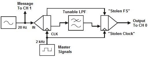
In Fig.2, the setup of this experiment PCM-Encoding & Decoding of band limited continuous signal is arranged with a little modification from the previous experiment of PCM encoding & decoding of continuous signal is that a Tunable LPF is put in between the PCM Encoder & PCM Decoder. The decoded wave of the band limited signal is shown in the Fig.3 i.e. sine wave decoded back again with the adjustment of LPF Gain & Frequency to smoothen the wave.
As you have seen, bandwidth limiting distorts digital signals. As you have also seen, digital receivers such as PCM decoders have problems trying to interpret bandwidth limited digital signals. The trouble is, bandwidth limiting is almost inevitable and its effects get worse as the digital signal's bit-rate increases.
To manage this problem, the received digital signal must be cleaned-up or "restored" before it is decoded. A device that is useful for this purpose is the comparator. Recall that the comparator amplifies the difference between the voltages on its two inputs by an extremely large amount. This always produces a heavily clipped or "squared-up" version of any AC signal connected to one input if it swings above and below a DC voltage on the other input. As you know, ordinarily we avoid clipping but in this case it's very useful. The bandwidth limited digital signal is connected to one of the comparator's inputs and a variable DC voltage is connected to the other. The bandwidth limited digital signal swings above and below the DC voltage to produce a digital signal on the comparator's output. Then, the variable DC voltage is adjusted until this happens at the right points in the bandwidth limited digital signal for the comparator's output to be a copy of the original digital signal.
Unfortunately, this simple yet clever idea has its limitations. First, bandwidth limiting can distort the digital signal too much for the comparator to restore accurately (that is, without errors). Second, the channel can cause the received digital signal (and the hence the restored digital signal) to become phase shifted. For reasons not explained here this can cause other problems for receivers.